

Aftermarket race-style bucket seats from Summit Racing were mocked up. Sounds simple enough but there are a few things to keep in mind when doing this in an A-body Mopar.
If you're installing stock bucket seats you can just drill holes at the factory dimples located in the floor on each side and drop 'em in. You should add reinforcing plates beneath the inboard holes as the factory did to prevent from tearing out the holes.
Fun fact: Ma Mopar engineered the engine to sit about 1.5 inches right of center in the engine compartment for more clearance for steering components. The trans tunnel is also offset to the right which means there's more room on the left for a seat than the right. The side to side seat hole spacing is different too.
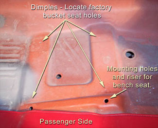
The aftermarket seats have a different mounting hole spacing (no surprise) - a little wider. I wanted to keep the seats centered relative to factory location and not interfere with the trans tunnel or the bench seat hump. The outer bucket dimples are the same distance from the door/rockers on each side so that's what I referenced. The other consideration is the fact that the floor isn't flat. In fact, the inboard holes are located in a slight recess. My solution was 3/4" angle iron: I could compensate for the lower inner holes (without spacers), clear some curvature near the bench seat mount, and give me a little clearance under the seat for hands or toes!
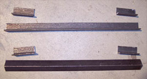
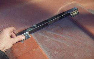
Each pair of custom mounting brackets is made from two 13" lengths of 3/4" angle iron and four 2" pieces for mounting tabs. Why 3/4"? I'm 6' 02" tall. With the old bench seat I didn't have a lot of head room - and that seat was worn out! I wanted to keep these seats low.
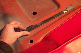
Here, after some welding and grinding, the brackets are sitting in their approximate final resting place. The mounting tabs on the inside bracket are welded so that they are about 1/8" lower than the bottom of the main piece to compensate for the change in floor elevation there. Don't want the seats to lean. Holes were then marked for seat to bracket and bracket to floor holes. Remember to measure 20 times and drill once!
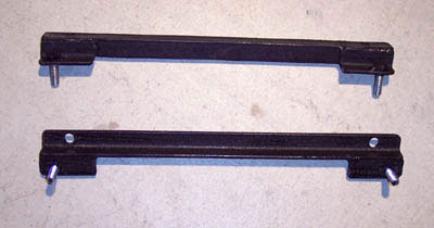
Here you can see a finished pair of mounting brackets sprayed in black wrinkle. I tack welded the bracket to floor bolts to make installation and removal of the seats easier. They actually retain the same front to rear hole spacing as factory (12"). In the lower bracket you can see the holes where they are mounted to the seat sliders (11" spacing).
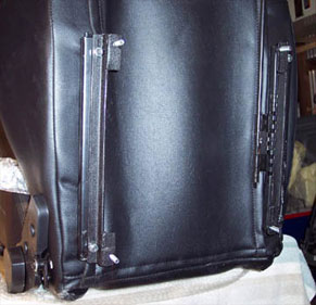
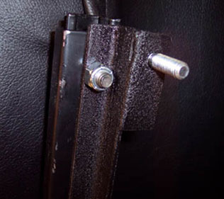
The brackets were then bolted to the bottom of each slider. A pair of slotted holes in each slider allows some adjustability.
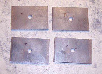
I then fabbed four 2"x3" reinforcing plates to be mounted under the inboard holes for strength. The factory had similar plates for bucket seat cars. The outer holes (bucket and bench) are already reinforced.
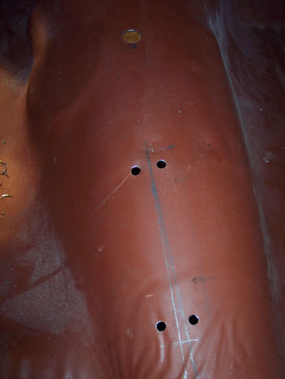
I drilled a couple of holes in the floor fore and aft of the main holes for plug welds, sprayed some weld-thru primer on top of the plates (future rust reduction), and then bolted the plates to the underside of the hole. The bolts held the plates firmly in place while I plug-welded them from inside the car.
I drilled a couple of holes in the floor fore and aft of the main holes for plug welds, sprayed some weld-thru primer on top of the plates (future rust reduction), and then bolted the plates to the underside of the hole. The bolts held the plates firmly in place while I plug-welded them from inside the car.
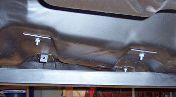
A little grinding of the welds, some paint, and "Zero Rust" finished them off.
(Right) Plates have been plug-welded from inside and the seat bolted into place. That's a sub-frame connector passing underneath.
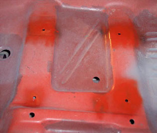
(Below) Holes and plug welds were touched up with a little Zero-Rust and rattle can orange.
(Right) Plates have been plug-welded from inside and the seat bolted into place. That's a sub-frame connector passing underneath.
(Below) Holes and plug welds were touched up with a little Zero-Rust and rattle can orange.
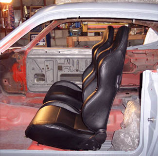
The finished mock-up. Way more comfortable than the old bench! More head-room for my 6'+ frame, great bolstering, and even some lumbar support.
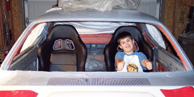
My son Austin took her for a test drive. (Jan '07)
My son Austin took her for a test drive. (Jan '07)
I decided to convert the column shift to a floor shifter so I located a floor shift steering column for sale on line and bought it. When it finally arrived it showed signs of previous abuse and incompetence. I completely tore it apart, media blasted everything, primed and painted the pieces and reassembled, replacing missing parts from the original column. There are no pics of disassembly, only reassembly. Disassembly is basically the reverse of what you’ll see here.
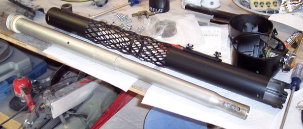
Here are some of the parts laid out. The silver shift tube was damaged on the donor so I reused the one from my original column. The shifter arm on the left end has been cut off. The shift tube serves no purpose now other than to support the lower third section of the column head/housing. If the assembly is to remain a column shifter, then the floor plate needs to go on the bottom of the black outer jacket before the shift tube is inserted, otherwise it won’t go on later.
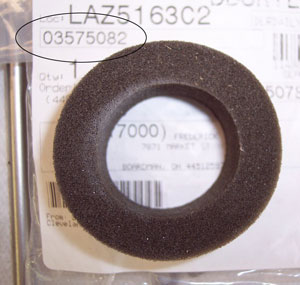
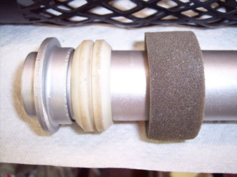
The lower bearing/bushing slides down over the shift tube. I reused the old one. It doesn’t do much anymore other than support the lower end of the shift tube inside the jacket. A new foam seal, still available from dealers (part number circled), is glued around the shift tube near the bottom. This will help prevent drafts and fumes from traveling up the inside into the passenger compartment.
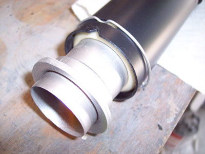
The shift tube is then slid into the jacket from the bottom. A snap ring secures the white plastic bushing.
Again, if you leave the shift lever on the bottom of the tube, you’ll need to install the floor mounting plate (two pieces plus rubber grommet) over the jacket first. Without the arm, they can go on later.
Again, if you leave the shift lever on the bottom of the tube, you’ll need to install the floor mounting plate (two pieces plus rubber grommet) over the jacket first. Without the arm, they can go on later.
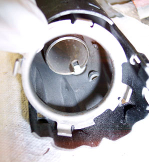
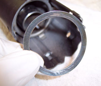
This odd shaped support ring press fits into the top of the jacket. It only goes in one way and will only go down so far. A wave washer sits on top. Both are liberally coated with grease first.
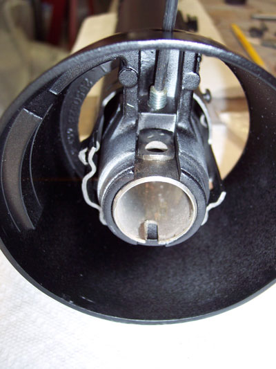
The lower third section of the column housing slides over the end of the shift tube and is secured with a 1/8” allen head set screw.
Below, I had to re-tap one of the screw holes of the middle section of the column housing. Then the lock cylinder and lock plate mechanism go in. It’s coated in grease.
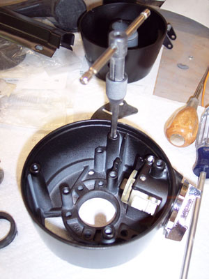
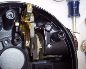
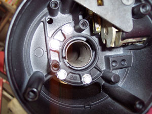
The jacket is slid up through the lower third section of the housing and the middle section of the housing is attached to it using 4 long sheet metal screws.
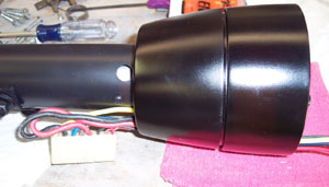
Ignition switch wiring is slid through the openings on the two housing sections.
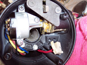
The ignition switch is secured with 3 screws. The key buzzer switch is laying loose in the lower right.
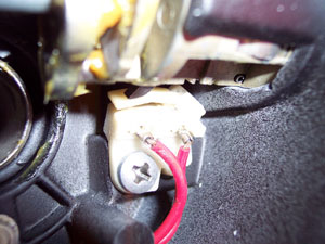
The key buzzer switch is secured just below the key cylinder with one or two screws depending on the year.
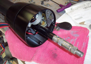
The steering shaft is then slid in from the bottom...
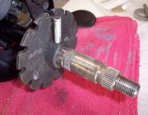
And the lock plate is slid on until the holes aligned...
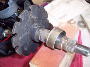
Supporting the end of the shaft, the roll pin is driven in. Then a locking collar slips over the end of the lock plate, covering the roll pin.
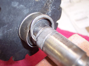
The lower snap ring goes on before turning attention to the upper third section of the housing.
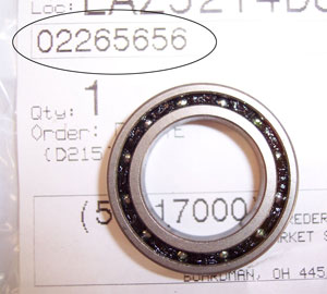
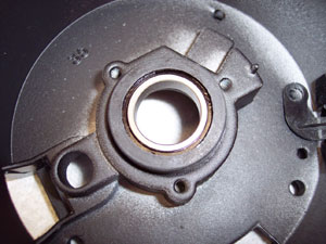
The upper bearing of the donor column was shot. The one in my original column felt okay but I went ahead and replaced it anyway. The bearings are still available (part number circled) and quite common across various models. It fits into a rubber iisolator and the two are pressed by hand into the upper section of the housing.
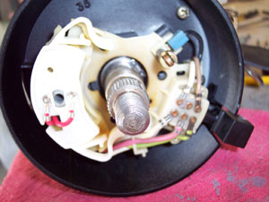
The upper section of the housing is slid over the end of the shaft and secured with 3 screws to the middle section of the housing. An upper snap ring goes on the shaft to retain the bearing.
Then, the turn signal wiring is slid through the openings in the housing and the assembly placed over the end of the shaft. Since they’re getting kind of spendy I re-used the donor switch. One of the cancelling tabs was broken, so I bought a switch repair kit from NAPA for about $20. It’s the whiter colored plastic piece.
Then, the turn signal wiring is slid through the openings in the housing and the assembly placed over the end of the shaft. Since they’re getting kind of spendy I re-used the donor switch. One of the cancelling tabs was broken, so I bought a switch repair kit from NAPA for about $20. It’s the whiter colored plastic piece.
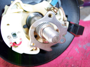
A retainer holds the switch assembly in place with 3 screws.
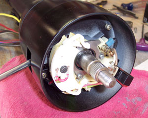
I cleaned up my original turn signal lever and installed it with the long black machine screw that passes through the switch assembly.
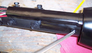
A wiring “trough” tames the wires that exit the housing. It’s held in place with two tabs and two screws. I reused my metal one. Later troughs were plastic.
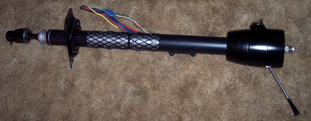
And here’s the finished column with the floor plate in place and rebuilt steering coupler.
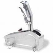
Next up on the interior was to get the floor shifter installed. I chose a B&M Magnum Grip Pro Stick. I like the looks of it as it pays homage to the slapstick shifter.
First thing was to get it located on the trans tunnel. Since the tunnel is offset to the passenger side, if I had stuck it in the middle of the peak, it would sit closer to the passenger seat than the driver’s. I measured the cockpit of the car and determined where center was and marked it. Naturally, that put it a little left of center on the tunnel. Rather than bolt the shifter to the floor, which obviously isn’t flat, I decided to use studs. I drilled the holes for the studs and the shifter cable. The forward holes for the shifter are just behind the trans crossmember. Any farther forward and I’d be in the crossmember. This actually locates the shifter just about where it would pop out of the floor on a factory floor shift car.
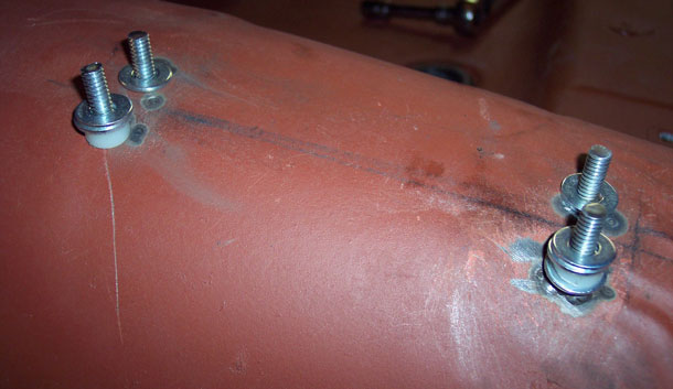
I welded the studs (bolts actually) to the underside of the tunnel making sure to keep everything properly spaced and plumb so that the shifter would slip cleanly over the top of them. I also used a combination of washers and nylon spacers ground at an angle to keep the shifter level. I also ground the ends of the studs to a height that wouldn’t interfere with other parts associated with the shifter. Too long and they’ll interfere with the hitch pins that hold the shifter cover on.
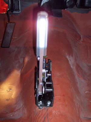
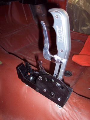
And here it is installed. The shifter cable will pass from the shifter through a 1” hole in the tunnel. I got a rubber grommet in the electrical section of a hardware store for a 1” hole. The hole in the center of the grommet is 3/4”. The cable will route around the passenger side of the trans, across the bellhousing and to the supplied bracket that mounts on the tranny. A length of Cool It Thermo-Sleeve will (hopefully) protect the cable from melting from exhaust system heat - a common problem.
See the Reassembly page for final details on the interior.
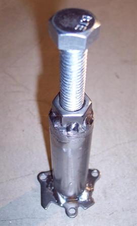
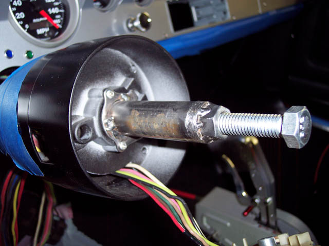
While I have no disassembly pictures, and my column came apart by hand, I did make a tool later that when I decided to replace the ignition switch. After you remove the upper snap ring next the bearing (which you'll see later below) the upper section of the column may not come off simply by wiggling it. That's why dealers had tool C4044 to "press the shaft out of the bearing". I made a tool that mimics the factory service tool from a nut, bolt, tubing, and an extra turn signal switch retainer - works great! ....On with reassembly.
 |
 |
 |
 |
 |
 |
 |
 |
 |
© 2013 JP Herrick Enterprises - All Rights Reserved
Site updated: January 2014

